
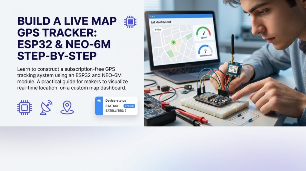
Building an esp32 gps tracker with live map is one of the most rewarding projects for engineering students and self-taught makers — it combines embedded hardware, wireless protocols, and real-time data visualization in a single build. Whether you want to track a bicycle, monitor a vehicle, or replicate systems like the college bus tracker described in a 2024 Nature study on real-time student transport safety, the ESP32 gives you a capable, low-cost foundation. Before you start, bookmark the free IoT dashboard tools for ESP32 guide — you will need a visualization platform once your hardware is transmitting coordinates.
The biggest friction point most beginners hit is not the wiring — it is choosing a dashboard that does not lock essential features behind a paid plan. A borewell pump controller running 16 telemetry fields on Blynk’s free tier exhausted 100,000 messages within days at a five-second update interval. The same logic applies to a GPS tracker streaming latitude, longitude, speed, and altitude every few seconds. Free alternatives exist, and this guide will show you exactly how to put the full pipeline together without spending on subscriptions.
What Is an ESP32 GPS Tracker With Live Map
Definition and Background
An esp32 gps tracker with live map is a microcontroller-based system where an ESP32 board reads position data from a GNSS module — most commonly the u-blox NEO-6M or NEO-M8N — and transmits that data over Wi-Fi or cellular to a cloud endpoint. The cloud endpoint then renders the coordinates on an interactive map interface, typically using the Leaflet.js open-source mapping library or a similar tile-based renderer. The ESP32’s dual-core Xtensa processor, built-in Wi-Fi, and generous GPIO set make it far better suited to this task than earlier AVR-based boards, which lacked native wireless capability.
The GPS module communicates with the ESP32 over a UART serial interface using the NMEA 0183 sentence format. Your firmware parses those sentences — specifically the GPRMC and GPGGA lines — to extract latitude, longitude, altitude, speed, and fix quality. That parsed payload then travels via MQTT or HTTP to your chosen dashboard platform.
Why It Matters
Real-time location tracking is no longer a niche requirement. Projects like Brett Smith’s Backcountry Beacon — an ESP32-S3-powered off-grid navigation tool covered on Hackster.io — demonstrate that hobbyist-grade hardware can now match the functional scope of commercial tracking units. For students, building a live GPS tracker proves competency across hardware integration, serial protocols, networking, and cloud data handling — all in one submission-ready project.
Key Benefits of Building a Live GPS Tracker on ESP32
Primary Advantages
- Low cost: An ESP32 development board and a NEO-6M GPS module together cost well under $15 from most component suppliers, making the esp32 gps tracker with live map approach accessible to students on tight budgets.
- No subscription required: Pairing the tracker with a free-tier IoT dashboard eliminates the recurring fees that plague commercial tracking SaaS products.
- Extensible firmware: The Arduino-compatible toolchain means you can add peripherals — an OLED display, an SIM800L cellular module, or a VL53L5CX ranging sensor — without switching ecosystems.
- Open map rendering: Leaflet.js paired with OpenStreetMap tiles gives you a fully functional, attribution-compliant live map at zero licensing cost.
Who Benefits Most
Engineering and computer science students benefit most directly — a working esp32 gps tracker with live map demonstrates practical IoT skills that internship interviewers value. Freelancers building fleet tracking MVPs for small logistics clients can prototype the core system before pitching. Budget-conscious makers exploring ideas similar to OpenTrailPaper’s e-paper bike computer (which turns LILYGO hardware into a GPS-enabled trail device) can adapt the same firmware and visualization stack covered here.
Step 1 – Step 7: How to Get Started Building the Tracker
Step-by-Step Overview
Follow these seven steps in order. Each step is self-contained, and skipping ahead typically causes firmware or connectivity failures that are difficult to debug after the fact.
Step 1 — Gather your components. Collect an ESP32 DevKit board (any 38-pin variant works), a NEO-6M GPS module with ceramic antenna, jumper wires, a USB cable, and a breadboard. Optionally add a 0.96-inch I2C OLED display for on-device coordinate readout.
Step 2 — Wire the GPS module. Connect the NEO-6M TX pin to ESP32 GPIO16 (RX2) and the NEO-6M RX pin to ESP32 GPIO17 (TX2). Power the module from the ESP32’s 3.3 V rail — confirm your specific module’s voltage tolerance before wiring, as some breakouts include a voltage regulator and accept 5 V on VCC. Ground both boards together.
Step 3 — Install the Arduino IDE and required libraries. Open the Arduino IDE, add the ESP32 board package via the Boards Manager URL (https://raw.githubusercontent.com/espressif/arduino-esp32/gh-pages/package_esp32_index.json), then install the TinyGPS++ library by Mikal Hart from the Library Manager. Also install the PubSubClient library for MQTT if you plan to use that transport.
Step 4 — Write and upload the parsing firmware. Use the sketch below as your starting point. It reads NMEA sentences from Serial2 and prints parsed coordinates to the Serial monitor. Verify a GPS fix before adding any networking code.
#include <TinyGPS++.h>
TinyGPSPlus gps;
HardwareSerial gpsSerial(2);
void setup() {
Serial.begin(115200);
gpsSerial.begin(9600, SERIAL_8N1, 16, 17);
}
void loop() {
while (gpsSerial.available() > 0) {
gps.encode(gpsSerial.read());
}
if (gps.location.isUpdated()) {
Serial.print(“Lat: “); Serial.println(gps.location.lat(), 6);
Serial.print(“Lng: “); Serial.println(gps.location.lng(), 6);
}
}
Step 5 — Add Wi-Fi and MQTT transmission. Extend the sketch to connect to your network using WiFi.begin(ssid, password) and publish a JSON payload — {"lat":xx.xxxx,"lng":yy.yyyy} — to an MQTT broker every 10 seconds. Use a public broker such as broker.hivemq.com on port 1883 for initial testing. Reduce the publish interval only after confirming stable connectivity, because frequent publishes are precisely what depleted free-tier quotas on earlier dashboard platforms.
Step 6 — Connect to a free dashboard and configure the live map widget. Sign up for Nodik, which offers four devices on its free tier with no credit card required — enough to run a real esp32 gps tracker with live map project rather than a crippled demo. Create a device, add a Map widget, and map the MQTT topic fields for latitude and longitude. Nodik renders the position on a Leaflet-based tile map in real time.
Step 7 — Field-test and refine update rate. Take the tracker outdoors with your phone hotspot as the Wi-Fi source. Verify that the map widget updates with each MQTT publish. Adjust the publish interval to balance responsiveness against data usage — a 10-second interval is a practical default for most tracking use cases.
Tools and Resources You Need
- Arduino IDE 2.x or PlatformIO in VS Code
- TinyGPS++ and PubSubClient libraries
- Free MQTT broker (HiveMQ public broker or a self-hosted Mosquitto instance)
- A free IoT dashboard — see the full comparison in the free IoT dashboard tools for ESP32 roundup
- NEO-6M or NEO-M8N GPS module with an active antenna if used indoors for testing
Common Mistakes to Avoid
Mistake #1 — Testing Indoors Without an Active Antenna
The NEO-6M’s passive ceramic patch antenna cannot acquire a satellite fix through a concrete ceiling. Builders who test their esp32 gps tracker with live map setup entirely indoors spend hours debugging what is actually a signal problem, not a firmware problem. Place the module near a window or move outdoors the moment you need to verify the NMEA output contains a valid fix status (the A character in the GPRMC sentence’s status field, versus V for void).
Mistake #2 — Ignoring MQTT Message Volume on Free Dashboard Tiers
Publishing location data every second produces 86,400 MQTT messages per day per device. Many free-tier platforms cap daily or monthly message counts at levels that sound generous until you do the arithmetic for a continuous live GPS tracker. Choose a dashboard platform whose free tier is structured around device count rather than message count — that architecture is far more forgiving for streaming sensor projects.
How to Prevent Them
Conduct your first GPS fix test outdoors within five minutes of powering the module — cold start acquisition on the NEO-6M typically takes under 60 seconds with a clear sky view, according to the u-blox NEO-6 hardware integration manual. For message volume, set your publish interval to 10 seconds or longer during development and only shorten it after confirming your dashboard’s quota policy. Batching multiple fields into a single JSON payload per publish also reduces message count without sacrificing data richness.
Tips for Getting the Best Results
Pro Tips
- Use a UART buffer: Wrap your NMEA reading loop in a non-blocking pattern so the ESP32 does not stall on serial reads while handling Wi-Fi tasks. The TinyGPS++ library’s
encode()method is designed for this pattern. - Store the last known fix: If Wi-Fi drops, cache the most recent valid latitude and longitude in RAM and publish them on reconnect rather than discarding the data.
- Add a timestamp field: Include the GPS-derived UTC time in your MQTT payload. Dashboards that support time-series storage can then plot a full route replay, not just the current position — turning your esp32 gps tracker with live map build into a route recorder as well.
- Enable deep sleep between publishes: For battery-powered deployments, put the ESP32 into deep sleep for 9 of every 10 seconds. The GPS module can be powered via a GPIO-controlled transistor switch so it also powers down between fix cycles.
Advanced Techniques
Once your basic live map pipeline is stable, consider geofencing. Subscribe to your own MQTT topic from a second ESP32 or a server-side script, compare incoming coordinates against a defined bounding box, and trigger an alert when the tracker exits the zone. This pattern is what underpins the college bus safety systems described in transport research literature — the same architecture scales from a single student project to a multi-vehicle fleet. You can also export your MQTT data to a time-series store and render historical tracks using a secondary visualization layer, giving your esp32 gps tracker with live map build genuine analytical depth beyond point-in-time position display.
Frequently Asked Questions About ESP32 GPS Tracking Projects
Can I use this project without Wi-Fi? Yes. Swap the ESP32’s Wi-Fi transport for a SIM800L GSM module communicating over GPRS. The firmware structure remains identical — you replace the WiFiClient object with the GSM library’s client object. This approach suits vehicle tracking where Wi-Fi hotspot coverage is unavailable. Note that a cellular data SIM adds a small monthly cost.
How accurate is the NEO-6M? The u-blox NEO-6M datasheet specifies a horizontal position accuracy of 2.5 metres CEP (Circular Error Probable) under open-sky conditions with a clear satellite view. Accuracy degrades in urban canyons due to multipath reflections. For most student and hobby tracking projects, 2–5 metre accuracy is more than sufficient.
Is the live map in the dashboard real time? The map updates each time a new MQTT message arrives at the broker and the dashboard client processes it. In practice, the perceived latency between the tracker publishing and the map pin moving is typically under two seconds on a stable connection — fast enough for vehicle or bicycle tracking where positions change gradually.
What is the difference between a GPS tracker and a GPS logger? A tracker transmits coordinates to a remote dashboard in near real time, enabling live map visualization. A logger stores coordinates locally (on an SD card or in flash memory) for post-processing. An esp32 gps tracker with live map does the former, though you can add local logging as a redundant data layer using the same hardware.
Can I run multiple trackers on one free dashboard account? Nodik’s free tier supports four devices simultaneously, which means you can track up to four ESP32 units — each publishing from a unique MQTT client ID and topic — on a single account without upgrading. That is sufficient for a student cohort running a shared fleet tracking experiment or a freelancer demonstrating a proof-of-concept to a client.
Do I need to register the GPS device with any authority? Passive GPS receivers — modules that only receive satellite signals and do not transmit RF themselves — require no radio license in most jurisdictions. The Wi-Fi or cellular transmitter on the ESP32 side must comply with local type-approval regulations, but using a certified ESP32 development board covers this requirement. Always verify the rules in your specific country before deploying a live tracking device in a vehicle.
Ready to put this into practice? Try it free — no credit card required.
Start visualizing your ESP32 GPS data live on Nodik's free tier — 4 devices, no card required, ready in minutes.
More in this series
- Best Free IoT Dashboard Tools for ESP32 (2026 Guide)
- ESP32 Push Notifications Without Blynk: 5 Ways to Stay Free
- ESP32 IoT Project Checklist Before Submission: The Complete Guide
- ESP32 Home Automation Relay Control From Phone: Complete Setup Guide
- ESP32 Smart Irrigation System for Agriculture: Step-by-Step Build Guide
- ESP32 DHT22 Temperature Dashboard: Build Your Own in 6 Steps
- ESP32 Water Level Monitor With Live Dashboard: A Real-World Case Study
- ESP32 Project Ideas for Final Year Students: 10 Builds That Actually Impress (2026)
Get new posts by email
Pick the topics you care about — we only email you when something new is published in them.